

Dry cooler
Outdoor air cools the liquid in the coil. Modular fans keep it serviceable and the corrosion-resistant build suits open-air siting; fan speed control and adiabatic pre-cooling extend it into hot weather.
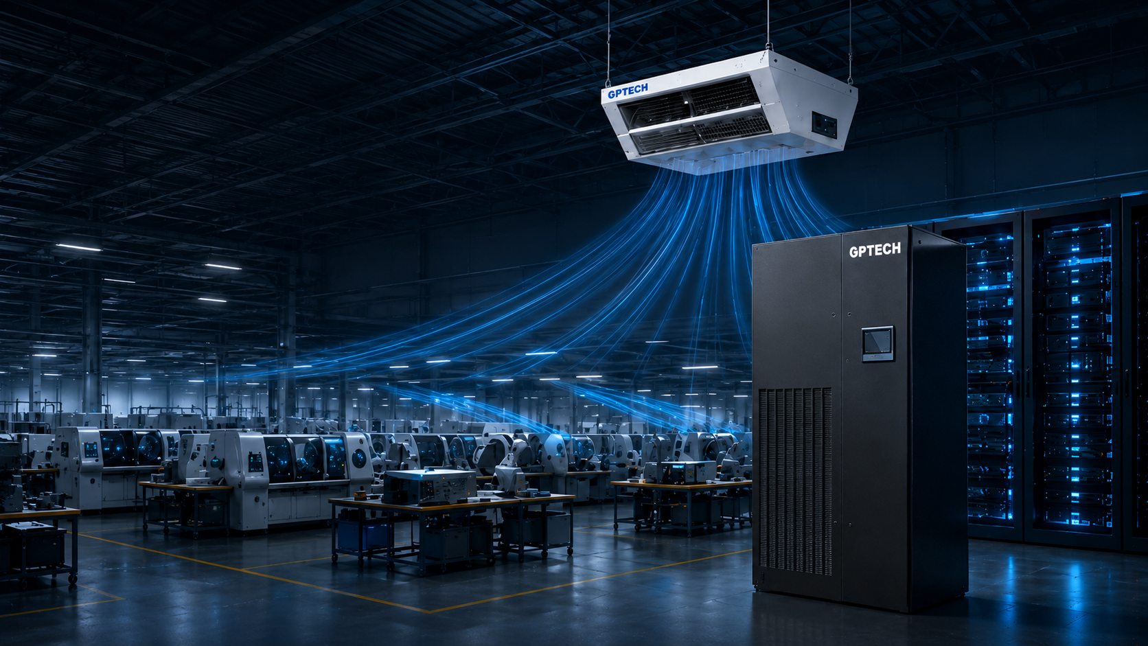
A continuous, measurable path for heat — from the cold source through the CDU to the cold plate.
The system starts at the IT load and works outwards: cold source, primary distribution, CDU, secondary ring, and the rack itself.
Precision air conditioning and the liquid loop carry the IT load together; the cold source rejects it continuously.
Towers, dry coolers, chillers and condensers combined to suit the climate, the load and the water available.
Outdoor air cools the liquid in the coil. Modular fans keep it serviceable and the corrosion-resistant build suits open-air siting; fan speed control and adiabatic pre-cooling extend it into hot weather.
Evaporative rejection, and the efficient choice where water is available. Selection has to account for water quality, consumption, drift control and winter protection.
Carries year-round or peak mechanical load; selected on supply temperature, efficiency and redundancy.
For direct-expansion or refrigerant systems, configured by heat rejection, noise and ambient.
Uses low outdoor air or water-side free cooling to cut compressor hours.
Switches between cold-source modes on load, climate and supply/return temperature.
The facility-side system that ties cold source, pump sets and CDUs into one supply and return.
Prefabricated mains, hydraulic balancing, sectioning valves and online monitoring meet today's load while leaving a clear boundary for phased expansion and for switching a branch out to work on it.
Twin supply and return mains, branch isolation and the key measuring points are laid out together, so flow can be balanced, a fault located and a zone maintained without draining the rest.
Stainless prefabricated pipework, distribution manifolds and quick connectors between the CDU and the rack.
Assembled, cleaned and tested in the factory, then fitted on site as modules. The pipework takes glycol, propylene glycol or deionised water, and integrates ports for temperature, pressure, flow and leak detection. Valves allow a section to be isolated and worked on while the rest keeps running.
Prefabricated in the factory, which takes the welding and the contamination risk off the site.
Manifold distribution and sectioning valves: steady supply, and a branch that can be worked on.
Sensor ports left in place, so the loop grows with the rack count instead of being rebuilt.
The unit that separates facility water from the fluid touching the servers — and takes on circulation, filtration, make-up, monitoring and control.
The central heat-exchange hub for a mid-to-large liquid-cooled cluster.
Cabinet, circulation pumps, plate heat exchanger, valves, expansion tank, filter and controls. Secondary fluid runs from the CDU to the cold plates, picks up the heat, and hands it to the primary side across the plate exchanger — a closed loop.
| Item | 300 kW | 600 kW | 800 kW | 1400 kW | 2500 kW |
|---|---|---|---|---|---|
| Rated flow L/min | 450 | 900 | 1000 | 1200 | 3700 |
| Primary supply | 32℃ | 32℃ | 32℃ | 32℃ | 32℃ |
| Secondary supply | 36℃ | 36℃ | 36℃ | 36℃ | 36℃ |
| Flow turndown | 10%–100% | ||||
| Supply | 380–480V | ||||
4U, sited next to the IT load so the secondary run stays short.
| Item | 40 kW | 80 kW | 160 kW |
|---|---|---|---|
| Secondary flow L/min | 60 | 99 | 160 |
| Primary supply | 35℃ | 35℃ | 30℃ |
| Secondary supply | 40℃ | 40℃ | 35℃ |
| Pumps | Dual | ||
| Supply | 220V AC | 48V DC | 48V DC |
A way into liquid cooling for a room that has no facility water to connect to.
Pumps, a liquid-to-air exchanger, fans, filter, expansion tank and controls. Simple to install, and aimed at single-rack liquid cooling inside a conventional data hall.
Rear-door fans, a liquid-to-air exchanger, pumps, controller and pipework, cooling the fluid with cold-aisle air. Suits high-density rows and retrofits into an existing room.
Choosing between them Where facility water is not available or the retrofit window is short, L2A is worth evaluating. Where there is a stable cold source, L2L comes first.
Reference configurations transcribed from the GPTECH liquid-cooling brochure. Final model, medium and operating conditions are set by the technical selection document, not by this page.
Room, row and rack level — chosen on the size of the hall, the heat density, the airflow you can organise and the cold source available.
Small rooms, telecom nodes
Scale halls, phased build-out
High-density row cooling
Standalone racks, local hot spots
The small unit is built for continuous year-round duty in a tight footprint, single-cool or close-control as the site needs. The modular unit covers scale halls and phased projects, with module redundancy, inverter control and several supply-air arrangements.
In-row units sit in the rack line, pushing cold air straight into the cold aisle and taking hot air back nearby, which removes the losses of a long path. Rack units serve a single enclosure in a closed loop, out of reach of whatever the room air is doing.
Selected on Per-rack heat load, airflow organisation, cold-source type, the temperature and humidity band you can allow, and the redundancy grade.
Leak, water quality, condensation and plant sequencing — across the rack, the CDU and both loops.
Coverage runs from the server and manifold through the CDU to both the primary and secondary pipework. Sensing cable and point sensors are zoned by area, and an alarm can drive valves, pumps or the supervisory system rather than only lighting a lamp.
pH, conductivity and turbidity measured continuously, so degradation, contamination or corrosion shows up as a trend — and a fluid change is scheduled on evidence rather than on the calendar.
Operating limits move with supply temperature, room conditions and dew point.
CDU, pumps, valves, cold source and BMS held to one operating mode.
Temperature, pressure, flow, water quality, alarms and plant state on one screen.
Load tracking and inverter control, to cut the hours spent running inefficiently.
Six stages, each with an input, an output and something to verify — so equipment interfaces and system boundaries do not come apart at the seam.
Heat load, room conditions, cold source, redundancy and growth targets
System boundary, hot and cold paths, pipe sizing and hydraulics, control logic
CDU, ring mains, cold-source plant and precision AC matched to the duty
Drawings, BOM, interface review, factory assembly and test
Site connection, hydraulic balancing, alarm and mode-switch verification
Training, maintenance plan, spares advice and continuing technical response
The delivery rule Clear boundaries · clear interfaces · clear responsibility · clear verification.
Rack density, room conditions and the cold source you have — enough to come back with a loop.